Development
Turning on and off a light, the smart way
.jpg)

One of my passions in life is integrating things together. So, as a summer project, I decided to try my hand at DIY smart home automation with electronic circuits and sensors. And I’m here to say that it’s easier and cheaper than you think. Here’s a tutorial I wish I had before I started.
The first thing I’ve tried is to turn on and off a light with the push of a button. All you really need is a couple of batteries, a light, a button and voilà!
Your browser does not support HTML5 video.
Not very interesting… But it’s okay, we’re going to do it the smart way.
The Raspberry Pi
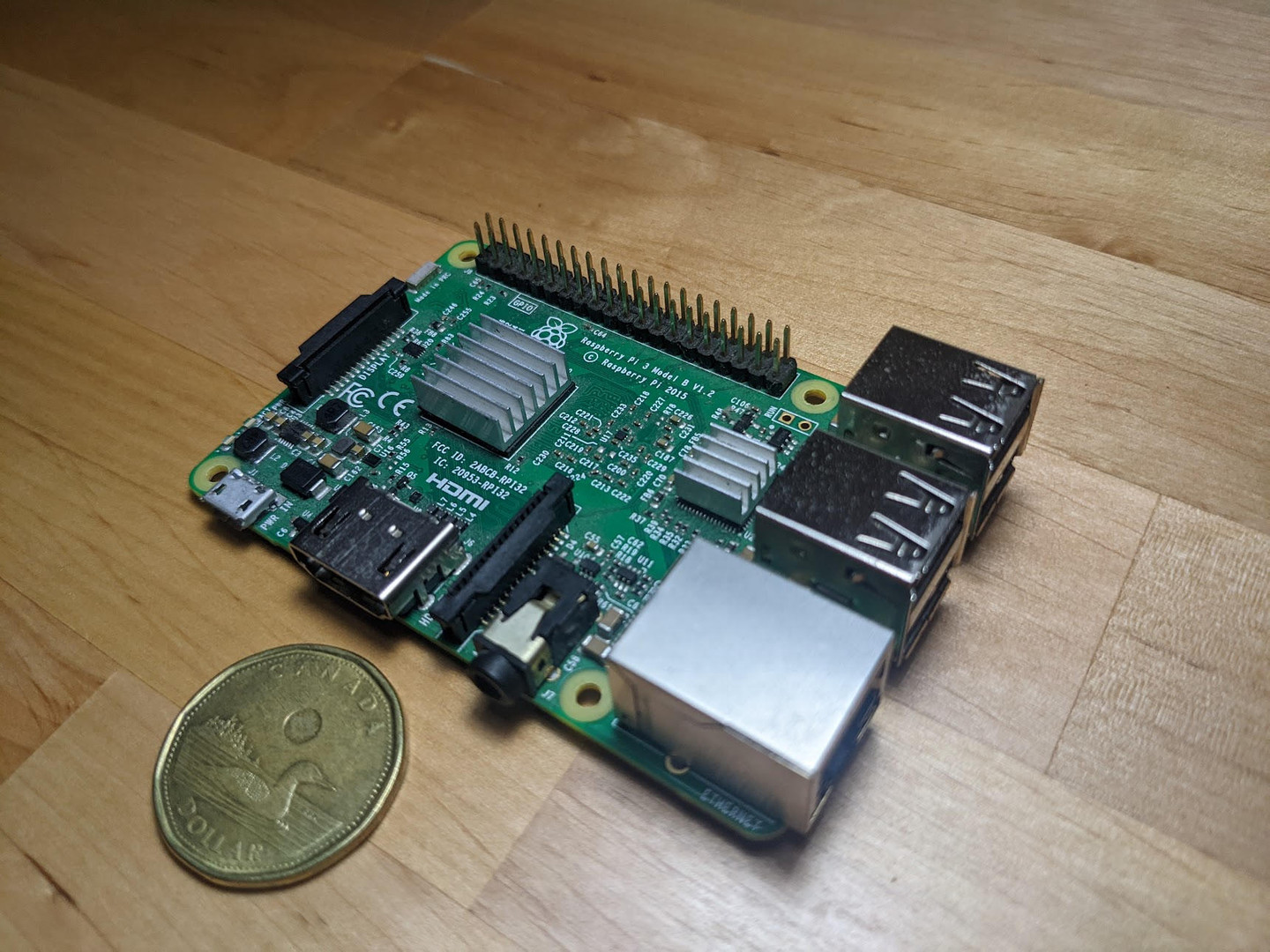
This is a Raspberry Pi. It’s a fully-fledged computer that sells for $45 CAD in its base variant. For its price, it’s remarkably well furnished. Besides being able to run the Linux operating system, it has:
- 4 USB ports
- Gigabit Ethernet
- 3.5mm Headphone Jack
- WiFi
- Bluetooth
- Up to 8GB of RAM, depending on the variant
- Up to two HDMI ports each supporting 4K monitors, depending on the variant
- A General-Purpose Input/Output (GPIO) 40-pin header
It’s the GPIO header that’s going to be particularly interesting for automating. The GPIO header is a series of 40 pins that either:
- Provides 3.3 Volts
- Provides 5 Volts
- Is grounded
- Is reserved for special use
- Provides the ability to either control the voltage of the pin or to obtain the voltage applied to the pin from software (called GPIO pins)
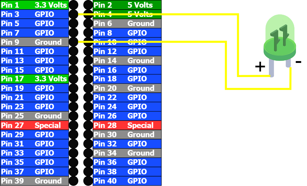
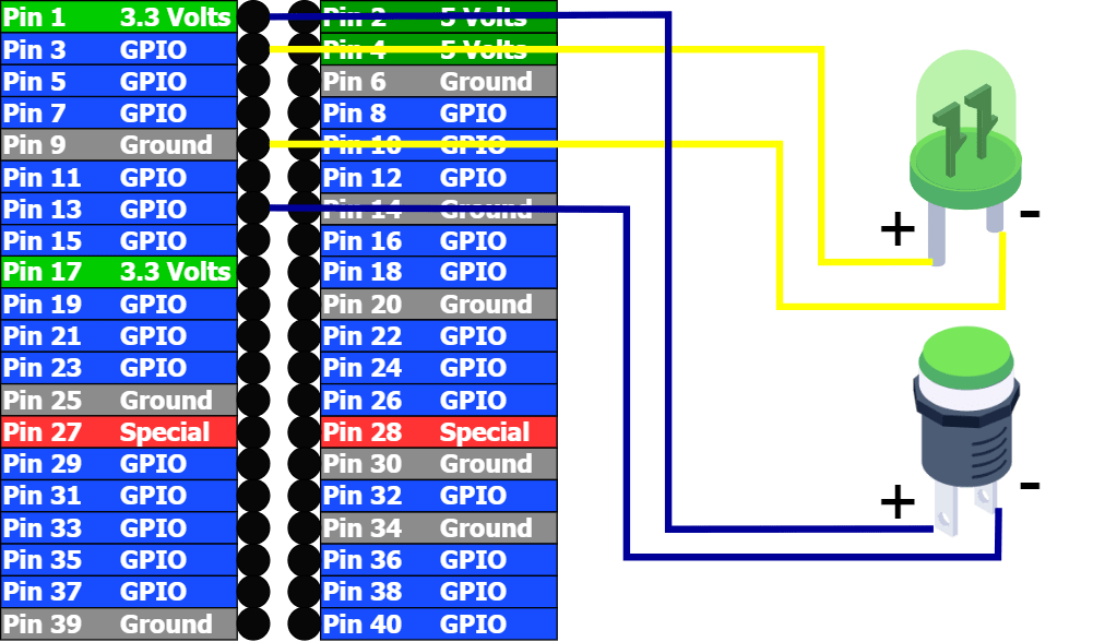
Each pin is typically identified by a number. Here’s a schematic identifying those pins (this will be useful later):
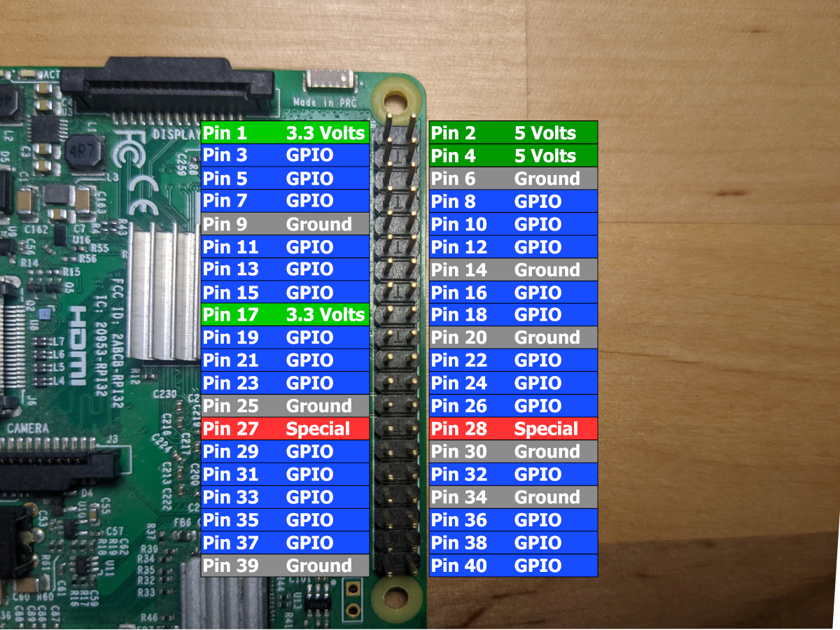
There’s an alternative numbering schema possible, but we will keep things simple in this tutorial. Also note that GPIO pins can support at most 3.3 volts, so you cannot plug a 5 Volts pin to a GPIO pin. Very important to know if you don’t want to fry your Raspberry Pi…
Voltages and GPIOs
Voltage can be described as a difference in potential energy. A nice analogy is a waterfall: the water at the top of a waterfall has a high potential energy, and as it falls, the potential energy gets lower. We say that it’s potential energy because water itself does not carry energy, but tasks can be accomplished with falling water: put a turbine to generate electricity, put rocks to eventually erode them, etc. If there wouldn’t be a difference in height between the top of the waterfall and the bottom of the waterfall (effectively, just flat ground), then there wouldn’t be any potential energy released. You can think of the height of the waterfall as the voltage of an electronic circuit.
When it is said that an electrical source provides 3.3 Volts, it is describing the difference between the high potential energy state (referred as +, 1 or HIGH) and the low potential energy state (referred as -, 0 or LOW). In the Raspberry Pi, the ground pins represent the low state and the pins that provide 3.3 Volts have a potential energy relative to that ground. The pins identified as GPIO can be controlled via software to either output a HIGH or LOW state, or to be able to read what voltage is applied to the pin.
Understanding Breadboards
Despite its unrelated name, breadboards are a useful tool for prototyping electronic circuits. Anything modeled on a breadboard can be turned into an electronic circuit that you may find in toys for instance.
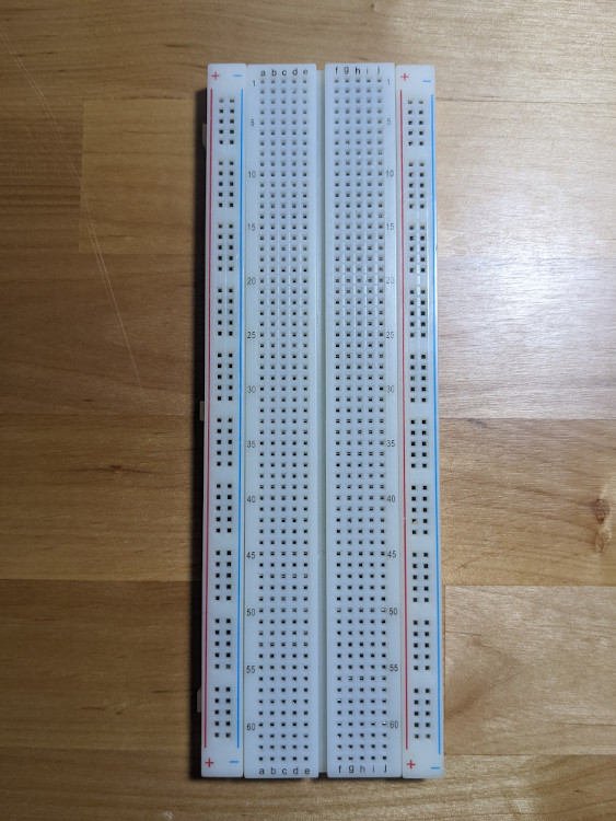
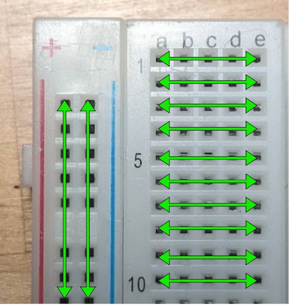
Breadboards are a series of holes connected in the back by wires in a specific manner. People designing the circuit would then take wires to connect some of the holes together. From the back, there are two paths that current can take on a breadboard. If we focus on the left half of the board, the current flows up and down on the two leftmost columns of holes. They typically carry the + and -. Then, the five rightmost sets of holes are connected into rows. Each row is independent from the others. The same layout is mirrored on the right side of the breadboard.
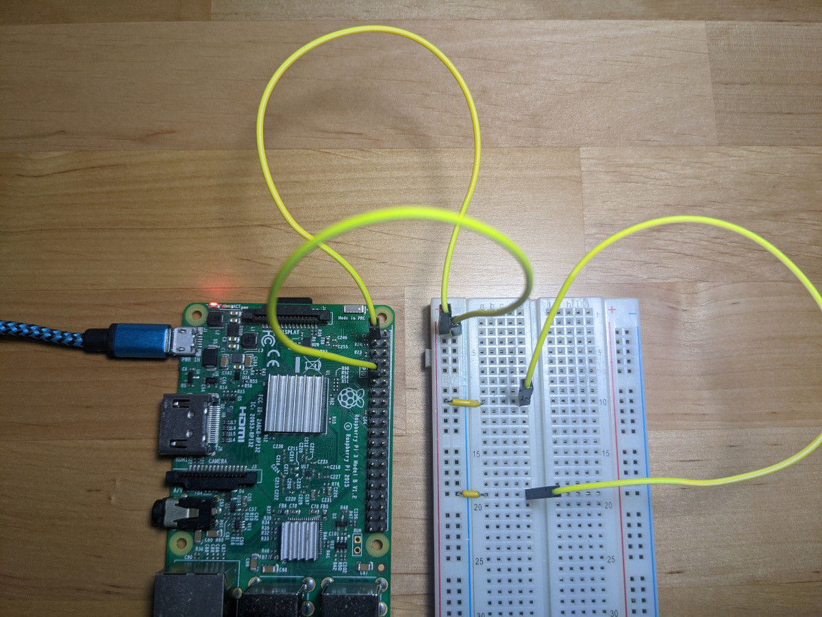
It’s typical to connect the power source to the + and - columns to the columns, then use small wires to carry the current from the two columns into specific rows, and finally connect the various electronic components on the rows. Here’s an example of a closed circuit, meaning the current flows from the 3.3 Volts on pin 1 directly to the ground on pin 9:
On and Off
Now that we have established the basics, we will start by turning on and off a light from software. In order to do this, we need to be able to switch between sending a HIGH and LOW signal to the light using a GPIO pin that is controllable over software. GPIO pin 3 will be used for that purpose, whereas pin 9 will be the ground or LOW. Note that any pins identified as GPIO and ground could have worked. Also, an interesting standard to know is that the long pin on the light should be connected to the +. Lights that you buy should be compatible with a 3.3 Volts signal, otherwise you will need resistors in your circuit. Here's the schematics of the first circuit.
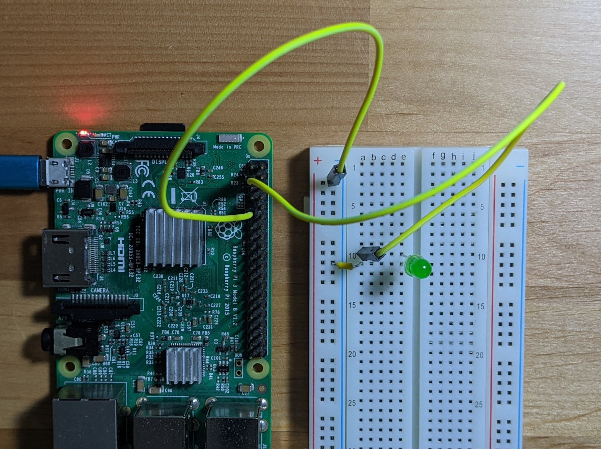
And here is what the circuit looks like:
Then, we’ll switch our attention to software. We will be using the Python programming language to control the state of the light, but nothing advanced. There are many tutorials to install Python if it’s not already installed on your distribution of Linux. You will then need to install a library called RPi.GPIO to be able to control the GPIO pins. To do so, run the following command: pip install RPi.GPIO
Here’s the code that we will use to turn on and off a light:
import RPi.GPIO as GPIOfrom time import sleepGPIO.setmode(GPIO.BOARD)GPIO.setwarnings(False)GPIO.setup(3, GPIO.OUT, initial=GPIO.LOW)state = GPIO.LOWwhile(True): if(state == GPIO.HIGH): state = GPIO.LOW else: state = GPIO.HIGH sleep(1) print(f'Sending {state} to GPIO 3') GPIO.output(3, state)
Here’s a quick breakdown of what’s happening:
Lines
Description1, 2Importing libraries, notably the RPi.GPIO library which allows us to control the state of the GPIOs4We’re telling the library we’ll be using a particular numbering schema for pins that starts with 1 for the top left pin, consistent with the picture of the GPIO header used in this tutorial.5We’re disabling the warnings that the pins are already used with another software because you may be running this code a couple of times.6Here’s the interesting part. We’re telling the Raspberry Pi that we will be using GPIO pin 3 in an output mode. The output mode allows the GPIO pin to be set in a HIGH mode (ie: 3.3 volts relative to ground) or LOW mode (ie: 0 volts relative to ground). We’re also mentioning that we want to start in a LOW mode so that the light does not start already lit up.8We’re declaring a state variable to store the state of the light.9This is an event loop. If you’ve coded video games, you might be familiar with this concept. This is the main loop in our software that will repeat until the software is stopped.10, 11, 12, 13This is a simple logic that toggle the content of the state variable, either HIGH or LOW14We’re pausing the execution of the software for 1 second (or 1 Hertz). Combined with the while loop, this means that the light will turn on or off once per second.15Printing the state we’re about to set to the light16We’re telling the Raspberry Pi to either send a HIGH or LOW signal (respectively 3.3 volts or 0 volts, depending on the content of the state variable) to the pin 3.
And here’s the outcome!
Your browser does not support HTML5 video.
Adding a button
We’ll complexify things a bit by adding a button to the circuit. The button will control the light: pressing down on the button will turn on the light, and releasing the button will turn it off.
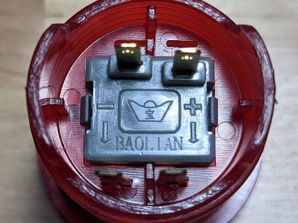
A button simply closes the circuit when pressed. Whatever voltage applied on the button will not go through when the button is not pressed, and will let it through when pressed (effectively acting as a wire). We will need to send 3.3 volts to the + side of the button, and connect the - side of the button to a GPIO pin that’s able to sense the voltage coming out of the button. When the button is going to be pressed, the GPIO will be able to see that 3.3 volts (or a HIGH signal) is received from the button. For this purpose, we will be using pin 1 for the 3.3 volts signal and pin 13 as the voltage-reading GPIO pin. Again, any GPIO pin would have worked. Note that with this particular model of button, the underneath shows which are the positive and negative poles.
Here’s the schematics we’ll implement. Note that there’s no change to the light circuit.
And here it is on the breadboard:
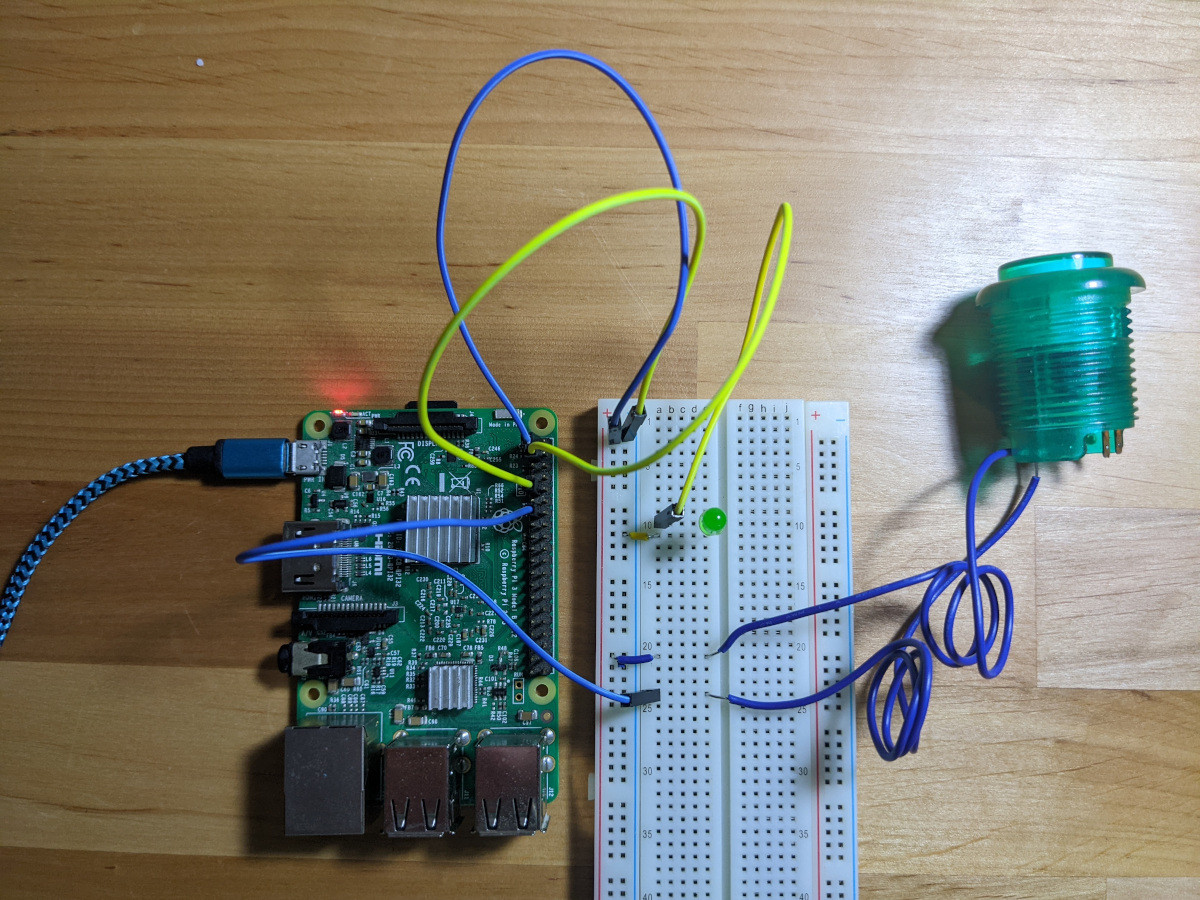
This is becoming a bit of a rat’s nest, especially in pictures. But the yellow wires represent the light’s circuit, whereas the blue wires represent the button’s circuit.
We will also tweak the code we’ve previously used in order to read the voltage coming out of the button. The main change is that we will now rely on the state of the button to determine the state of the light.
import RPi.GPIO as GPIOfrom time import sleepGPIO.setmode(GPIO.BOARD)GPIO.setwarnings(False)GPIO.setup(3, GPIO.OUT, initial=GPIO.LOW)GPIO.setup(13, GPIO.IN, pull_up_down=GPIO.PUD_DOWN)state = GPIO.LOWprevious_state = GPIO.LOWwhile(True): sleep(0.05) state = GPIO.input(13) GPIO.output(3, state) if(state != previous_state): print(f'State went from {previous_state} to {state}') previous_state = state
Here’s another explanation of the code. For the sake of brevity, the emphasis will be on the main changes compared to the last code breakdown.
Lines
Description7We tell the Raspberry Pi to expect an input on pin 13. We also tell it to ignore anything in-between 0 volts and 3.3 volts by mentioning that pin 13 will be connected to a Pull Up-Down button.12Our previous input loop was being executed once per second. In order to have a responsive light when we press the button, the loop needs to be executed much more often than previously. In this case, we are executing the loop every 0.05 seconds (or 20 times per seconds, or 20 Hertz)13We are obtaining the state of the GPIO pin 13. Since we set up pin 13 as a Pull Up-Down pin, we can expect either a HIGH or LOW result.14We are giving the state obtained at line 13 to the pin 3 which controls the light.
And here’s the outcome!
Your browser does not support HTML5 video.
Only the beginning
Nobody would be using such an elaborate method to turn on and off a light when pressing a button: As mentioned in the introduction, a battery, light and button would do the trick. But consider this: I have shown how to read an input into Python, and how to provide an output from Python. You could apply the same logic with a multitude of other sensors to create your own IoT / smart device. Here are a couple of examples of sensors from a $45 CAD 37-sensors kit:
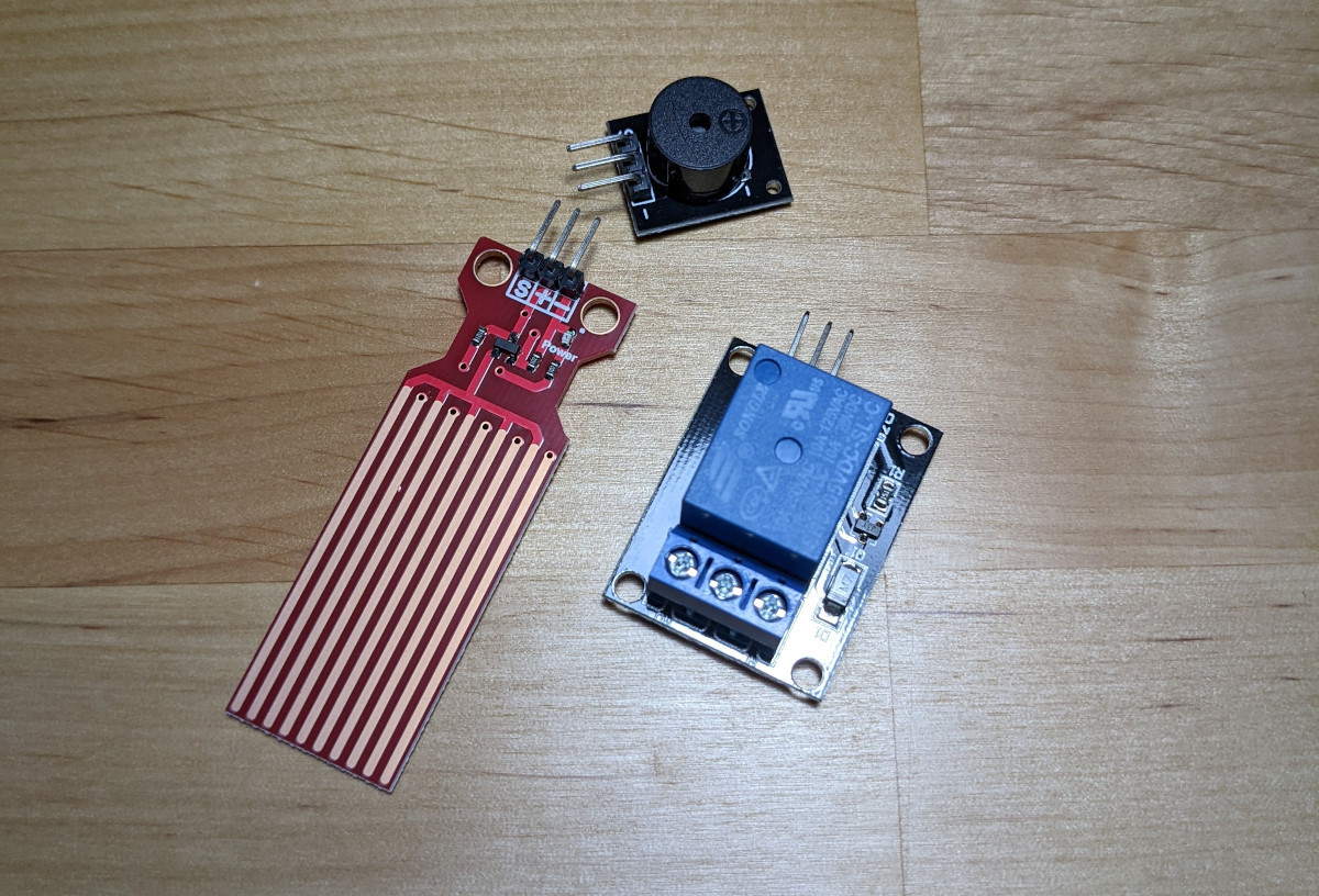
The water level sensor sends a non-zero voltage if there’s water detected. The passive buzzer emits a sound when a voltage is applied, and the relay lets 120 volts (the same voltages as home appliances in North America) go through only when a 3.3 volts signal is applied to the small pins.
With these three modules, you could easily design a system that detects if there’s flooding in an area, rings the buzzer, stops electricity from reaching nearby appliances and sends a notification through WiFi. At that point, your imagination (and the variety of sensors that exists) is the limit.
Header image by Carlos Alberto Gómez Iñiguez
Push button and diode icons created by smashingstocks - Flaticon

Did this article start to give you some ideas? We’d love to work with you! Get in touch and let’s discover what we can do together.